 |
| |
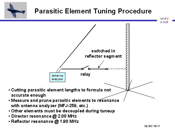
Slide 11 of 19
Notes:
The parasitic elements needed to be carefully tuned to the proper resonant frequencies.
Simply cutting the lengths according to formula or to the dimensions in the computer model
is not accurate enough in the real world, when considerations such as the velocity factor
of insulated wire and environmental effects are taken into account. We strongly
recommended direct measurement of the resonance frequency of the director and reflector.
To do this, the corner of each element is temporarily opened and an antenna analyzer (such
as the MFJ-259, which we used) is inserted at this point. By injecting RF into the element
with the analyzer and measuring the SWR vs. frequency, the resonance can be determined at
the point of minimum SWR. The lengths of the horizontal director and reflector segments
are pruned to the resonant frequencies determined by the computer model: 2.00 MHz for the
director and 1.90 MHz for the reflector. (The high resonant frequency of the reflector may
seem odd, but appears to be a consequence of the sloping geometry of the element). While
tuning one element, it is important that the the tower and the other parasitic element not
couple and corrupt the measurement. (We are measuring self-resonance of the element, not
mutual coupling resonance). To do this the tower is electrically opened from ground at its
base, and the other parasitic elements are best lowered or removed completely during
tuneup.